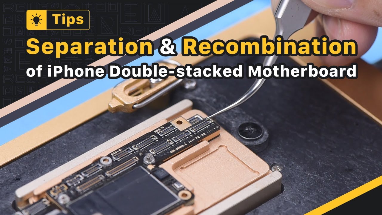
Lately, REWA Academy pupils provided responses that both layers commonly fall short to fit very closely in double-stacked motherboard repair work There are also big voids, triggering pseudo soldering In response, we will certainly share tips and also notes when separating and also recombining double-stacked motherboard Remove foam on the motherboard prior to heating Please be kept in mind that we do not recommend beginners to warm the motherboard with a warm air weapon Because the motherboard may obtain heat erratically as well as deform A professional motherboard home heating system is what we recommend To facilitate later elimination of the reasoning board, drive a screw on the reasoning board Puncture the tape with a Sculpture Knife The reasoning board and center layer are soldered with low-temperature solder paste So the most effective temperature level for the heating system will certainly be 155 ° C-165 ° C Push the reasoning board gently with tweezers when the temperature level reaches 165 ° C If the reasoning board is loose, the tin has melted Clamp the screw to eliminate the logic board Eliminate the signal board Get rid of thermal oil with a Sculpture Blade Thermal oil have to be gotten rid of totally Or else, the thermal grease will touch the logic board to generate pseudo soldering in recombination Connect the signal board to the holder Use a round of Paste Flux Remove tin on the bonding pad with Blowpipe at 365 ° C and Solder Wick Tin on the bonding pad need to be entirely gotten rid of The residual tin will influence the succeeding soldering Clean the bonding pad with PCB Cleaner Clean the logic board with the same method Please do not damage parts around the bonding pad of the logic board while cleansing It is essential to examine if the bonding pad is cool after cleansing Affix the signal board to the Reballing System Placed the reballing stencil ready to make sure that it is pushing against the signal board To prevent the solder paste from streaming right into the motherboard void, place a steel plate Use a layer of low-temperature Solder Paste Clean off excess solder paste with a Lint-free Wipe Eliminate the reballing pattern Check if solder paste on the signal board is complete While applying solder paste, please ensure that solder paste have to have a certain humidity If the solder paste is too completely dry, it will adhere to the reballing pattern when the stencil is removed Consequently, the solder paste on the signal board will not be uniform, which can quickly result in bad soldering Placed the signal board on the 165 ° C Heating Platform to heat Stop home heating after the solder balls are developed Apply a tiny amount of Paste Change after the signal board has actually cooled Align the logic board with the signal board Keep heating on the 165 ° C Heating Platform When the solder change spills and logic board sinks, push the logic board gently with tweezers to guarantee the two layers fit carefully The nudge has to be gentle and also tiny Clean the motherboard with PCB Cleanser after the motherboard has actually cooled down If you find the motherboard deformed while recombining, you can place the motherboard on a flat board and also secure it with an elastic band Press two sides of the motherboard carefully To stay clear of crushing elements, please put a soft paper under the motherboard Following, we will certainly share another recombination approach The approach can be taken if the center bonding pad is not harmed When the tin melts, eliminate the logic board in a vertical manner with tweezers It can be seen that there is a steel pad of 0.05 mm density around the signal board at a particular range This steel pad is made to keep a 0.05 mm void between the reasoning board and also the center layer, avoiding the solder rounds from bridging while soldering You only need to remove thermal oil on the motherboard when the repair service is done Maintain original tin on the bonding pad Apply a small amount of Paste Flux Lastly, line up the reasoning board with the signal board When the temperature gets to 165 ° C as well as the tin thaws, transform the power off Press two ends of the logic board with tweezers till the motherboard has actually cooled down The logic board and the signal board fit carefully by doing this There will be no bridging as well as solder balls spillover Check out REWA Academy if you intend to discover more repair work skills We have complete program plans for motherboard medical diagnosis and also repair service capability enhancement Click the web link in the remark section to purchase motherboard repair service training course bundles Thank you for enjoying as well as feel cost-free to leave a remark


